Hi
I am new to assembler programming and am trying to get a simple program up and running on a PIC12F675 using a PICKIT2

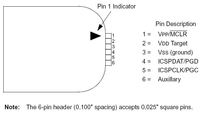
I have wired up the circuit using pins 1-5 on the PICKIT2 programmer according to this diagram:

PIN1 MCLR to PIC PIN4
PIN2 VDD to PIC PIN1
PIN3 VSS to PIC PIN8
PIN4 ICSPDAT to PIC PIN7
PIN5 ICSPCLK to PIC PIN6
PIN6 AUX to PIC PIN5 (not used?)

The problem is in the assembling of the code. My original code is:

processor     12F675	;set the correct PIC type

GPIO    EQU     05h
TRISO   EQU     85h

	ORG	0x000
        GOTO    MAIN

MAIN:   BSF     03h,5    ;Go to Bank 1
        MOVLW   B'000000';Put 00110 into W
        MOVWF   85h      ;Move 00110 onto TRISO
        BCF     03h,5    ;Come back to Bank 0

START:  MOVLW   B'111111';put 00001 into W
        MOVWF   GPIO	 ;move contents of W onto GPIO
        ;MOVLW   b'000000';put 00000 into W
        ;MOVWF   GPIO	 ;move contents of W onto GPIO
	GOTO    START
END

I use the following commands to assemble to code and upload/run it on the PIC12F675

; gpasm flash.asm                                   --assembles the program
; pk2cmd -P pic12f675 -M -F flash.hex               --burns the program to the MCU
; pk2cmd -P pic12f675 -A5 -T                        --powers the circuit at 5v
; pk2cmd -P pic12f675 -W                            --removes power from the circuit
; pk2cmd -PPIC12F675 -GF my_program.hex             --retrieves program stored on MCU
; gpdasm -p12F675 my_program.hex > my_program.asm   --disassembles program

The problem I have is that an LED attached to pin 2 (GP5) does not light up. I tried downloading the code and disassembling it which returns:

000000:  2801  goto	0x1
000001:  1683  bsf	0x3, 0x5
000002:  3000  movlw	0
000003:  0085  movwf	0x5
000004:  1283  bcf	0x3, 0x5
000005:  303f  movlw	0x3f
000006:  0085  movwf	0x5
000007:  2805  goto	0x5

Does anyone know what the problem is? The only issue I can see is in address 000003 where it seems to be pushing the direction flag data to address 05h rather than the address 85h specified in my original program. I also got the error:

flash.asm:19:Message [302] Register in operand not in bank 0. Ensure bank bits are correct.

I have spent ages trying to figure this out and would appreciate any help you can offer...

Thanks.

Solved the problem!
The solution was to firstly grab a copy of the p12f675.inc file and drop it into my project folder. Secondly I realised I had missed some critical information on P19 of the datasheet. Basically because the 12F675 is a low pincount chip all the pins can be either analog or digital and this has to be set in the CMCON register (low = digital and high = analog). The final error was ignoring the config settings.
Here is my working code:

; gpasm flash.asm                                   --assembles the program
; pk2cmd -P pic12f675 -M -F flash.hex               --burns the program to the MCU
; pk2cmd -PPIC12f675 -Y -Fflash.hex                 --verify the program
; pk2cmd -P pic12f675 -A5 -T                        --powers the circuit at 5v
; pk2cmd -P pic12f675 -W                            --removes power from the circuit
; pk2cmd -PPIC12F675 -GF my_program.hex             --retrieves program stored on MCU
; gpdasm -p12F675 my_program.hex > my_program.asm   --disassembles program

        LIST P=12F675
        #include <p12f675.inc>
        __config _CP_OFF & _BODEN_OFF & _MCLRE_OFF & _PWRTE_OFF & _WDT_OFF & _INTRC_OSC_NOCLKOUT
        ; _CP_OFF               ; code protection off
        ; _BODEL_OFF            ; brown-out reset enable bit off
        ; _MCLRE_OFF            ; MCLR bit used as a digital IO, internally tied to Vdd
        ; _PWRTE_OFF            ; power up timer enable bit off
        ; _WDT_OFF              ; watchdog timer disabled
        ; _INTRC_OSC_NOCLKOUT   ; 
        errorlevel -302

	org	0x000

MAIN:   bcf     STATUS,RP0  ;select bank 0
        clrf    GPIO        ;clear all GPIO pins
        movlw   B'111111'   ;set GP<5:0> to digital IO
        movwf   CMCON
        bsf     STATUS,RP0  ;select bank 1
        clrf    ANSEL       ;clear the analog selection register
        movlw   B'001100'   ;Put 00110 into W
        movwf   TRISIO       ;Move 00110 onto TRISIO
        bcf     STATUS,RP0  ; back to bank 0

START:  movlw   B'110011'   ;set GP<5:4><1:0> to high
        movwf   GPIO	    ;move contents of W onto GPIO
        movlw   b'000000'   ;set GP<5:0> to low
        movwf   GPIO	    ;move contents of W onto GPIO
	goto    START
END
Be a part of the DaniWeb community

We're a friendly, industry-focused community of developers, IT pros, digital marketers, and technology enthusiasts meeting, networking, learning, and sharing knowledge.