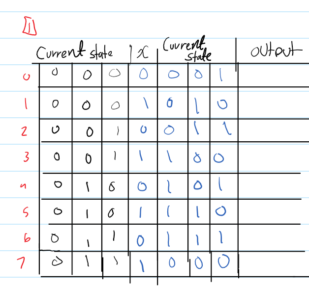
Design a three-bit counter using T-FFs. The counter has one input X. The counter counts odd numbers (1, 3, 5, 7) if X = 0 and counts even numbers (0, 2, 4, 6) if X = 1. If X = 1 and the current number is odd, the counter will go to the next even number. likewise, if X = 0 and the current number is even, the counter will go to the next odd.
**wanting to make have I did good so far ;-; been struggling a lot, next step is just drawing if I wasn't mistaken""

current_state.png

A three-bit counter can count from 0 to 7. In order to implement the desired behavior, we can use three T flip-flops to store the three bits of the count. The output of the first flip-flop will be the least significant bit (LSB), the second flip-flop will be the middle bit, and the third flip-flop will be the most significant bit (MSB).

The clock input of each flip-flop will be connected to a clock signal, and the T input of each flip-flop will be connected to the output of the previous flip-flop. The first flip-flop's T input will be connected to the input X. This will cause the flip-flops to toggle (change state) on each clock pulse if X is 0, and to not toggle if X is 1.

To implement the desired counting behavior, we need to introduce some additional logic. We can use AND gates to determine whether the current count is odd or even, and OR gates to determine the next value of the count based on the input X and the current count.

Here's an example of how the logic for the first flip-flop (LSB) might look:

           +----+
X ------->|    |--+
           | AND|  |
           +----+  |
           +----+  |
           |    |--+---> T
           | OR |--|
           +----+  |
           +----+  |
           |    |<-+
           | AND|
           +----+

The input X is used as the first input to an AND gate. The second input to the AND gate is the output of the second flip-flop (the middle bit), which indicates whether the current count is odd or even. The output of the AND gate is then used as one of the inputs to an OR gate. The other input to the OR gate is the inverted output of the second flip-flop (the middle bit), which indicates the next value of the count. The output of the OR gate is then used as the T input of the first flip-flop.

This same logic can be applied to the middle and MSB flip-flops, with the second and third flip-flops respectively being used to determine the current count and the next value of the count.

You can then draw a diagram of the entire circuit using T flip-flops, AND gates, and OR gates to implement a three-bit counter that counts odd numbers if X is 0 and even numbers if X is 1.

Be a part of the DaniWeb community

We're a friendly, industry-focused community of developers, IT pros, digital marketers, and technology enthusiasts meeting, networking, learning, and sharing knowledge.