Hi I need help on how to use LDR and ADC0804 in 8051 microcontroller.
So far I have this in my project but I want to replace the switch with LDR (dark activated).
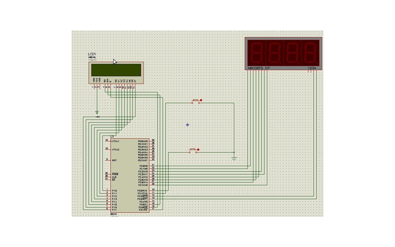
What happens here (attached file)is that I use the switch to decrement/increment the number of cars and when it reaches to 0(no available space) the LCD will prompt that it is full.
What I want is using a sensor(ldr) and a laser light so that when a car passes (the light will be broken) the ldr will send signal and decrement the number of spaces and vice versa( i'll be using two ldr one for exit the other for entrance).
attached is my design. Im using Isis Proteus 7.4 and the code below
DB0 EQU P1.0

DB1 EQU P1.1

DB2 EQU P1.2

DB3 EQU P1.3

DB4 EQU P1.4

DB5 EQU P1.5

DB6 EQU P1.6

DB7 EQU P1.7


EN EQU P3.7

RS EQU P3.6

RW EQU P3.5

DATA EQU P1


;7-Segment Display

enableDIGIT3 EQU P3.2

enableDIGIT4 EQU P3.3


ZERO    EQU   10001000b

ONE     EQU   10111110b

TWO     EQU   11000100b

THREE   EQU   10010100b

FOUR    EQU   10110010b

FIVE    EQU   10010001b

SIX     EQU   10000001b

SEVEN   EQU   10111100b

EIGHT   EQU   10000000b

NINE    EQU   10010000b

DOT     EQU   01111111b


MOV 20h,#ZERO

MOV 21h,#ONE

MOV 22h,#TWO

MOV 23h,#THREE

MOV 24h,#FOUR

MOV 25h,#FIVE

MOV 26h,#SIX

MOV 27h,#SEVEN

MOV 28h,#EIGHT

MOV 29h,#NINE


MOV R0, #20h

MOV R1, #22h


PDATA EQU P2 ; Connect 8 pins here


CLR 51h

LCALL LCD_WELCOME


Start:

	JB P3.1, check1

		SETB 50h

	check1:

	JB P3.0, check2

		SETB 52h

	check2:

		JNB P3.1, cont1

			JNB 50h, cont1

				CLR 50h

				LCALL INC_7SEGMENT

	cont1:

		JNB P3.0, cont2

			JNB 52h, cont2

				CLR 52h

				LCALL DEC_7SEGMENT

	cont2:

		LCALL SHOW_7SEGMENT

		LCALL SHOW_LCD

SJMP Start


SHOW_LCD:

	CJNE @R0, #ZERO, welcome

	CJNE @R1, #ZERO, welcome

		JB 51h, done_showlcd

		LCALL LCD_FULL

	sjmp done_showlcd

	welcome:

		JNB 51h, done_showlcd

		LCALL LCD_WELCOME

	done_showlcd:

RET

LCD_FULL:

	LCALL CLEAR_LCD

	LCALL INIT_LCD

	CLR RS

	MOV DATA,#086H

	SETB EN

	CLR EN

	LCALL WAIT_LCD

	MOV A,#'F'

	LCALL WRITE_TEXT

	MOV A,#'U'

	LCALL WRITE_TEXT

	MOV A,#'L'

	LCALL WRITE_TEXT

	MOV A,#'L'

	LCALL WRITE_TEXT

	MOV A,#'!'

	LCALL WRITE_TEXT

	MOV A,#'!'

	LCALL WRITE_TEXT


	SETB 51h

RET


LCD_WELCOME:

	LCALL CLEAR_LCD

	LCALL INIT_LCD

	CLR RS

	MOV DATA,#081h

	SETB EN

	CLR EN

	LCALL WAIT_LCD


	MOV A,#'P'

	LCALL WRITE_TEXT

	MOV A,#'A'

	LCALL WRITE_TEXT

	MOV A,#'R'

	LCALL WRITE_TEXT

	MOV A,#'K'

	LCALL WRITE_TEXT

	MOV A,#'I'

	LCALL WRITE_TEXT

	MOV A,#'N'

	LCALL WRITE_TEXT

	MOV A,#'G'

	LCALL WRITE_TEXT

	MOV A,#' '

	LCALL WRITE_TEXT

	MOV A,#'S'

	LCALL WRITE_TEXT

	MOV A,#'P'

	LCALL WRITE_TEXT

	MOV A,#'A'

	LCALL WRITE_TEXT

	MOV A,#'C'

	LCALL WRITE_TEXT

	MOV A,#'E'

	LCALL WRITE_TEXT


	CLR RS

	MOV DATA,#0C3h

	SETB EN

	CLR EN

	LCALL WAIT_LCD


	MOV A,#'A'

	LCALL WRITE_TEXT

	MOV A,#'V'

	LCALL WRITE_TEXT

	MOV A,#'A'

	LCALL WRITE_TEXT

	MOV A,#'I'

	LCALL WRITE_TEXT

	MOV A,#'L'

	LCALL WRITE_TEXT

	MOV A,#'A'

	LCALL WRITE_TEXT

	MOV A,#'B'

	LCALL WRITE_TEXT

	MOV A,#'L'

	LCALL WRITE_TEXT

	MOV A,#'E'

	LCALL WRITE_TEXT

	CLR 51h

RET


INC_7SEGMENT:

	CJNE @R1, #TWO, increment

	sjmp doneinc

	increment:

		CJNE @R0, #NINE, incr0

		MOV R0, #20h

		INC R1

		SJMP doneinc

		incr0:

			INC R0

	doneinc:

RET


DEC_7SEGMENT:

	CJNE @R0, #ZERO, dec0

	CJNE @R1, #ZERO, dec1

	sjmp donedec

	dec1:

		MOV R0, #29h

		DEC R1

		SJMP donedec

	dec0:

		DEC R0

	donedec:

RET


SHOW_7SEGMENT:

	MOV PDATA,#00h


   	setb enableDIGIT3

   	MOV     A,@R1

   	MOV PDATA,A

   	LCALL smallDelay

	clr enableDIGIT3


   	setb enableDIGIT4

   	MOV     A,@R0

   	MOV PDATA,A

   	LCALL smallDelay

	clr enableDIGIT4

RET


INIT_LCD:

	CLR RS

	MOV DATA,#38h

	SETB EN

	CLR EN

	LCALL WAIT_LCD


	CLR RS

	MOV DATA,#0Ch

	SETB EN

	CLR EN

	LCALL WAIT_LCD


RET


CLEAR_LCD:

	CLR RS

	MOV DATA,#01h

	SETB EN

	CLR EN

	LCALL WAIT_LCD

RET


WRITE_TEXT:

	SETB RS

	MOV DATA,A

	SETB EN

	CLR EN

	LCALL WAIT_LCD

RET


WAIT_LCD:

	CLR EN ;Start LCD command

	CLR RS ;It's a command

	SETB RW ;It's a read command

	MOV DATA,#0FFh ;Set all pins to FF initially

	SETB EN ;Clock out command to LCD

	LCALL smallDelay

	MOV A,DATA ;Read the return value

	JB ACC.7,WAIT_LCD ;If bit 7 high, LCD still busy

	CLR EN ;Finish the command

	CLR RW ;Turn off RW for future commands

RET


smallDelay:

		CLR TF1

		CLR TR1

		MOV TH1,#76

		MOV TL1,#01

		MOV TMOD,#01

		SETB TR1

		JNB TF1,$

RET